Raspberry Pi & Arduino: a laser pointer communication and a LDR voltage sigmoid
So I finally got some more time to play with my Raspberry Pi GPIOs and Arduino, this post will explain how to use a LDR (Photoresistor, Light Dependent Resistor) on the Raspberry Pi to detect a laser light emitted by an Arduino.
Plugging the laser module on Arduino
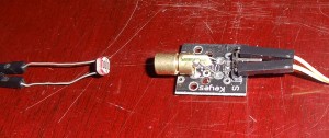
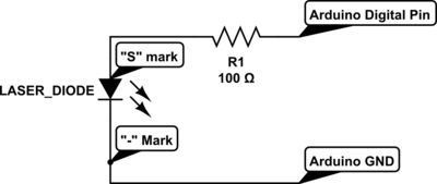
Isn’t easy to plug a module when you have no datasheet or some wiring schemes, the chances are that you’ll probably burn it if you provide a current greater than the supported. The module I have was bought on the DX.com and it came with 3 pins, “-” mark, “S” mark and a middle pin without any mark, I assumed that the “S” meant “Signal” and the “-” is the GND pin so I started plugging it on the Arduino pin 14 with a 440 ohm resistor and later I discovered that a 100 ohm resistor was giving the best bright laser without burning it; my advice is to not connect directly any of these modules without a resistor to limit the current, otherwise you’ll end up burning the diode. Here is the photo of the laser diode in front of the LDR:
Here is the wiring scheme to plug the laser on the Arduino:
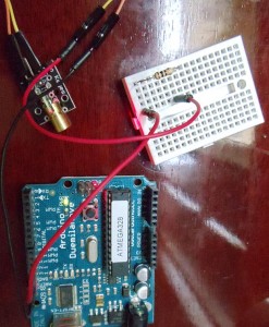
And here is the scheme on the breadboard of the Arduino with the 100-ohm resistor:
In order to test the laser, I just uploaded this program to Arduino, it just blinks the laser module:
int laserPin = 12;

void setup()
{
    pinMode(laserPin, OUTPUT);
    digitalWrite(laserPin, HIGH);
}

void loop()
{
    digitalWrite(laserPin, HIGH);
    delay(2000);
    digitalWrite(laserPin, LOW);
    delay(2000);
}
Look Ma, no ADC !
Since Raspberry Pi doesn’t come with an Analog-to-digital converter (ADC) like Arduino, connecting a LDR to its GPIOs pins is a little tricky (when you don’t have a Gertboard). The traditional approach is to use a capacitor and then time its charging according to the LDR resistance, this isn’t a precise measure, but it works well for most applications. What I’m going to do here is another approach, since I just want to measure if there is a laser light present or not (I’m not interested in the light energy), I don’t need to time the capacitor charging.
The first step was to measure the resistance that the LDR creates when the laser light is present, to do that I turned the pin 12 to HIGH on the Arduino and then measured the resistance on the LDR with the multimeter:
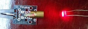
And the measure was roughly 200 ohms when the laser wasn’t pointing to the LDR (even with the daylight) the resistance was around the 2k ohm. Now we know that we have to build a circuit that is will use the interval of 0 ohms to 400 ohms (a good margin) as the threshold to activate/deactivate the GPIO pin of the Raspberry Pi.
The challenge now was how to create a circuit that would set the GPIO pin of the Raspberry Pi according to a defined threshold. It turns out that with the help of Oli Graser (see more about the circuit here), I discovered that you can create a voltage sigmoid with a voltage divider circuit outputting to a general transistor, and this is really awesome, can you imagine something like a logistic regression built in hardware ? Absolutely interesting.
Voltage divider and the “sigmoid” circuit
And here is the schematics of the voltage divider using the transistor as control of the GPIO pin:
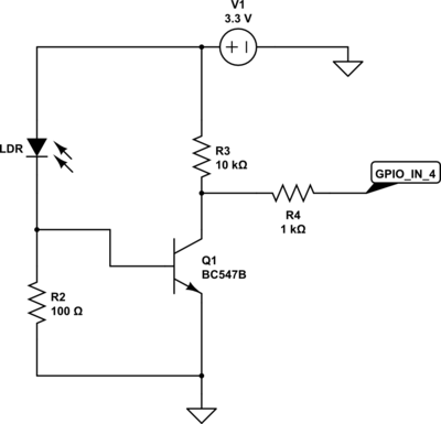
The first part of this circuit is the LDR and the R2 resistor, together they work as a voltage divider, when the laser is off, the LDR resistance is very high and then the voltage that goes to the base of the transistor Q1 (I used a BC547B) is very low, making the GPIO pin 4 state to go HIGH, when the laser is on, the LDR resistance is very low and the voltage going to the base of the transistor is enough to activate the circuit and makes the GPIO ping 4 state to go LOW since the current will flow to the path of less resistance, which is to the GND.
Below you can see the graph of the simulation I’ve done using the amazing Circuit Lab service:
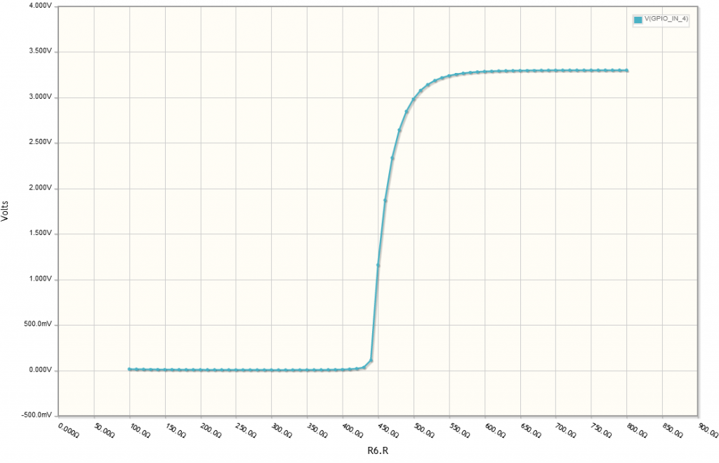
You can see in this graph is very similar to a sigmoid function, I’ve chosen the threshold by setting the voltage divider bottom transistor R2 to 100 ohms, you can adjust this as you wish to make, for LDR 500 ohms threshold I calculated 500 ohm * (0.7v / 0.3v) = 106 ohms (close to the 100 ohm resistor I used), the higher the bottom resistor value you use, the higher will be the center of the sigmoid.
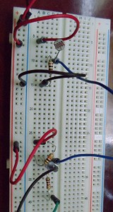
Here is the circuit already built on the breadboard:
And a zoom on the voltage divider part:
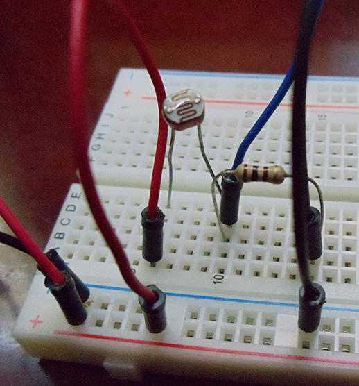
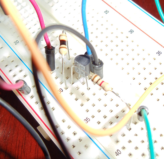
And a zoom on the transistor part:
And finally, the complete mount of the system:
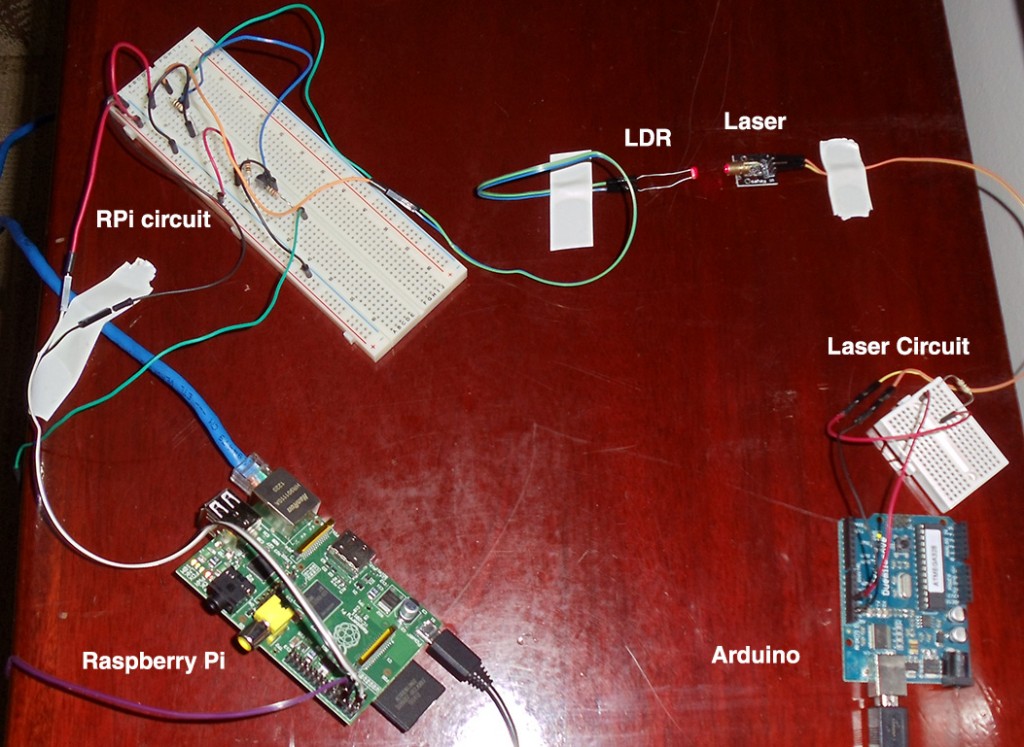
I used tape to fix the components on the table (there, I fixed it !).
Reading the GPIO state from Raspberry Pi using Python
To setup (as INPUT) and read the GPIO pin 4 of the Raspberry Pi (you can see the pins explanation here) I used the RPi.GPIO Python module, to install it just use “sudo pip install RPi.GPIO”, but you’ll need to have the package “python-dev” installed first if you’re using Raspbian distro. Here is the code to read and show the GPIO pin 4 value:
import RPi.GPIO as GPIO
import time

GPIO.setmode(GPIO.BCM)
GPIO.setup(4, GPIO.IN)

while True:
input_value = GPIO.input(4)
print "Input Value (PIN 4):", input_value
time.sleep(0.1)
And that is it, I hope you liked it and learned something new like I have learned to do this =) the next step will be to check how far I can transmit data using the laser pointer, I discovered that I can read using Python without any problems a change frequency of 2 milliseconds on the Raspberry Pi, this should be better using C code, I still need to implement the transmission protocol.

LDRs are sloooooow. Try using a phototransistor as the detector. If it is dark you should easily be able to get a clean 0/1 signal from the thing with a few passives.
There is just one problem: I don’t have a phototransistor hehe. Anyway, how much slow is a LDR compared to a phototransistor ? I need numbers.
Funny, but I think you would be able to do the same without the added price of the processors.
Yes, and also all circuits using Raspberry Pi lol.
hello…i want to ask u,i have a project similar to your project,but i have to use both arduino.my project have to transmit data for example the speed motor to the ldr at another arduino.i dont have idea how to connect these two arduino together.
Hello ainul, is your requirement to have laser and a LDR to do such communication ? Otherwise it would be better to use a serial, RF communication or another approach.
The speed of a light-dependent resistor depends on the light level. In bright light it might be in the millisecond range, but in very dim/dark conditions it can be seconds! A phototransistor would be a much better choice for medium speed serial data. They are widely available for less than $1 each. Do a search for “phototransistor circuit”. Even just 1 phototransistor + 1 resistor can be a useful detector.
Hey, thanks for the article, I’m a total beginner and really liked it!
I think I understood almost everything, but one computation:
500 ohm * (0.7v / 0.3v) = 106 ohms
Here, where are 0.7v and 0.3v coming from?
I will try to reproduce the same circuit, what should I adapt depending on my LDR resistance when lit?
Many thanks!
Hey, I kept on reading, and saw I had neglected a link, which now makes everything clear. However, you have a little typo:
500 ohm * (0.7v / 0.3v) = 106 ohms
should be
500 ohm * (0.7v / 3.3v) = 106 ohms
which makes a lot more sense 😉 (I was wondering where 0.3 was coming from, and you may consider adding a little note in your article explaining that 0.7V is trigger voltage or the transistor, that would make it perfect!)
Anyway, thanks a lot!
Thanks for taking the time to post this article!
I’m a beginner to electronics and have two questions:
1. if I want to modify your LDR circuit to have multiple LDRs, how would I do it?
2. will the LDR provide me with a range of values for the intensity of light or is it basically an ON/OFF device; if it will provide the intensity, will exposure to sunlight saturate it?
Thanks in advance for your response.
Why did you use the arduino for the laser instead of the raspberry pi?
Hello Kyle, no special reason other than having only one Raspberry Pi.
I like all your pages btw…
You may enjoy doing more non-ADC work, by using a comparator and pulsing the laser module. I was able to pulse a cheapo module at 10kHz.
I don’t know rasp PI, but I’ll wager there’s a comparator built in somewhere you can use. Not at export in the least, however, I think non-synchronos communication would be fun.
Cheers ! Love your work…
Thats a good idea, thanks for the feedback Daniel.
Great article, I am completely inexperienced when it comes to electronics, I can build a circuit but I dont really know what I am doing and why it workds 🙂
I have built the input side of the circuit, slight variation in that I am connecting to GPIO P24, however I always get a 1 returned, even if I block off the LDR with my finger. Any ideas why?
What I really want to do is have both circuits controlled by the same Pi with the laser pulsing and the LDR detecting the laser bouncing off an object. Is this possible and how would I achieve that with your circuitry above?
Thanks
Can you please suggest me some ways to connect two PCs using laser?
Thanks for the wonderful Introduction.
I have a MEGA board, I want to switch nearly 15 laser diodes using Arduino, is it possible? as Mega has many I/O pins.