Arduino WAN, Helium network and cryptographic co-processor
I was recently interested in the intersection of Machine Learning and RF and I was taking a look into LoRa modulation, which is based on Chirp Spread Spectrum (CSS), and ended up getting to know more about the Helium network. I still think that the most stupid piece of technology behind crypto mining is spending GPU/CPU/ASIC cycles to do proof-of-work (PoW), but in the Helium network, they did something quite interesting, which was to switch to something useful such as the proof-of-coverage instead of generating heat and burning energy. Therefore we can say that the miners are doing something useful by providing radio coverage, instead of purely generating heat.
It is impressive how many devices were already deployed in many countries, Helium network has now almost 500k devices providing RF coverage, which is quite nice. I’m based in London and here is the coverage map:

As you can see, there are a lot of hotspots already covering practically the entire city. Another quite interesting aspect of the Helium network is that they use H3 cells, which is very similar to the S2 cells I wrote about some time ago.
Although many people are interested in the mining aspect of the Helium network with expensive devices, this post is more about how to connect to the Helium network (use the service) with a very cheap Arduino that costs around 20 to 30 USD. This is the Arduino WAN 1310 seen below:
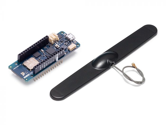
This is a very nice board because it comes with:
- SAMD21 Cortex®-M0+ (ARM MCU)
- The Murata radio module (that has AES on hardware, which is quite nice)
- The ATECC508 chip which is a cryptographic co-processor from Microchip (it doesn’t do encryption, but it has some quite nice features that I will show later how to use)
- Depending on where you buy, you can get the dipole antenna included too
At the time of writing this tutorial, there is basically no material on how to connect to the Helium and use its service for communication, neither many examples on how to use the functionality of the cryptographic co-processor, so I decided to do this quick tutorial to help people falling into the same situation.
Getting the device EUI
The DevEUI is a 64-bit globally-unique Extended Unique Identifier (EUI-64) assigned by the manufacturer (or owner) to the device. And you will need it because the Helium router has an XOR filter that filters packets from devices it knows only. So the first thing you will have to do is to get this ID from your Murata chip on your Arduino WAN, to do that, here is the code:
#include <MKRWAN.h>

LoRaModem modem(Serial1);

void setup() {
  Serial.begin(115200);
  while (!Serial);
  if (!modem.begin(EU868)) {
    Serial.println("Failed to start module on EU868 setting.");
    while (1) {}
  };
  Serial.print("Your device EUI is: ");
  Serial.println(modem.deviceEUI());
}

void loop() {
  while (1) {};
}
You will have to do the setup of the Arduino IDE first, but I skipped this because it is already described in the official tutorials. Then you need to install the MKRWAN library, and this is where the first problem comes, do not install the MKRWAN_V2 as it is not working to join into the Helium network at the time I’m writing this tutorial, and I spent a lot of time to realize that, so make sure you are using the MKRWAN library only. Once you run this code, it will print in your terminal the following message: “Your device EUI is: a3e10b3115246219” but with your DevEUI.
Adding the device into Helium console
Now, you need to register and login into your Helium console account and add a new device:
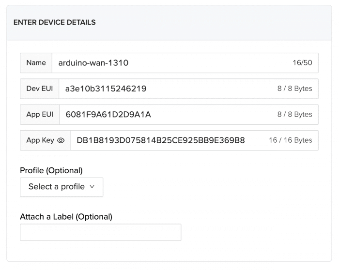
Note that the Dev EUI is the same as the one it printed for the device, and you will also need an App EUI and an App Key. Now, the AppEUI is an application identifier, and this can be public without any concerns. Now, the App Key is an AES-128 secret key that is shared with your device, only the console and your device know about it and it is used to provide end-to-end symmetric encryption of your payload data.
Once you add your device to the console, it might take around 20 minutes to add your device to the blockchain and update the XOR filters in the network. The next step is now to write the code to join the Helium network.
Connecting to the Helium network using LoRawan
Now if your device was successfully added, you can then join into the Helium network. There are two main joining protocols for LoRawan networks, however, Helium only supports OTAA at the moment, so make sure to use the correct activation protocol to join into the network. When you join using the OTAA protocol, another cryptographic key will be derived during the joining request to provide session security, however, keep in mind that your payload is always encrypted with your AES-128 key.
To connect into the Helium network, you can use the following code below:
#include <MKRWAN.h>

LoRaModem modem(Serial1);

String appEui = "[your AppEUI]";
String appKey = "[your app key]";

void setup() {
  Serial.begin(115200);
  while (!Serial);
  if (!modem.begin(EU868)) {
    Serial.println("Failed to start module on EU868 setting.");
    while (1) {}
  };
  Serial.print("Your device EUI is: ");
  Serial.println(modem.deviceEUI());
  Serial.println("Joining using OTAA...");
  int connected = modem.joinOTAA(appEui, appKey);
  if (!connected) {
    Serial.println("Something went wrong.");
    while (1) {}
  }

  delay(5000);

  modem.setPort(3);
  modem.beginPacket();
  modem.print("hello");
  int err = modem.endPacket(true);
  if (err > 0)
    Serial.println("Message sent!");
  else
    Serial.println("Error sending message.");
}

void loop() {
  while (modem.available()) {
    Serial.write(modem.read());
  }
  modem.poll();
}
This code will join the Helium network (if you are in a place where you have coverage, otherwise try to get closer to your window) and will then send a message and keep listening to messages received.
Note that the device needs the AppEUI that you defined and also the AES-128 shared secret AppKey that you defined earlier as well and that will guarantee end-to-end encryption of your payload. You are also free to add any other extra-level of security on your application layer as well.
If you have an SDR, you can see the LoRa chirps in the spectrum as in the image below:
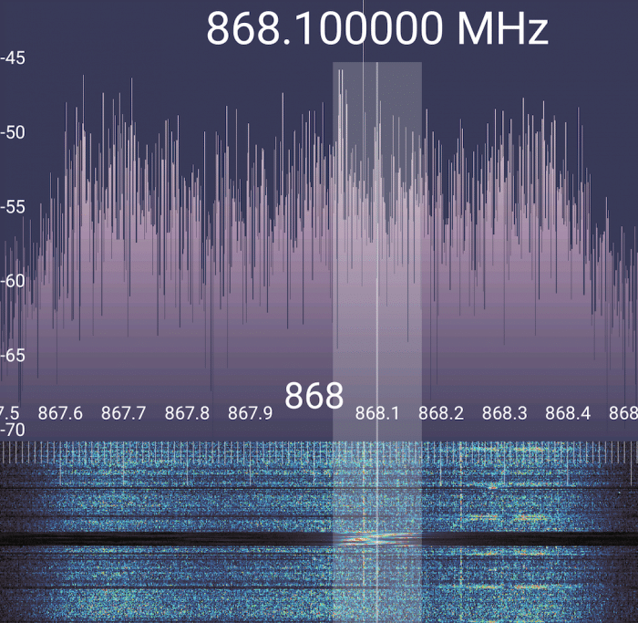
You will also be able to see all the messages, including the join-requests from your device at the Helium console. You will also see the list of devices that captured your packets and the signal strength of different hotspots around you.
To monitor the LoRa activity I used the following SDR below:
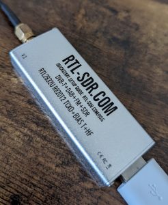
Which is a cheap one from RTL-SDR.com and comes with a telescopic dipole together so you can tune it to the frequency you want, I really recommend having one to debug and understand what is going on.
Cryptographic co-processor (ATECC508A)
As I mentioned earlier, the Arduino WAN 1310 also comes with a cryptographic co-processor that you can use for your applications to add another layer of security. This chip is the ATECC508A from Microchip, it is a very tiny and easy to use (using I2c) chip that you can also embed easily on other boards (you can find other breakout boards for it as well exposing the I2c interface).
As someone who worked before w/ cryptography, I really enjoyed this chip so I will be dedicating one section to it as I think it has some very cool functionality. This chip has hardware support for many FIPS-certified algorithms for public key infrastructure w/ elliptic curve (EC) cryptography. It supports ECDSA for the signing of messages and also ECDH to exchange symmetric secrets as well. It also has a high-quality FIPS random number generator and has support to store many private keys internally. Note that just as other security modules, the private keys generated on it will never leave this chip and cannot be read from it, so it adds a strong level of protection for the keys as you can only use them for operations of the chip and you cannot read externally.
First-time configuration
Now, there are not a lot of libraries implementing the I2c protocol to communicate and issue commands to this chip. One option is the Arduino library called ArduinoECCX08, but to be honest, I found that it doesn’t have many examples on how to use it, so I would recommend using the SparkFun library called SparkFun_ATECCX08a_Arduino_Library, which seems to have much more examples. This library from SparkFun wasn’t made for the Arduino WAN 1310 though, so I had to submit a PR to fix some issues regarding some processing times of the chip for the signing operation, but if you get the last version of this library you will be getting this fix and it should work fine with the Arduino WAN 1310.
Before using the chip, you will need to configure it and lock it, however, please pay attention that this can be done ONLY ONCE and if you use the configuration from the SparkFun library, it is mainly focused on signing and verification, so keep this in mind as you won’t be able to change it later, the chip will LOCK THIS CONFIGURATION PERMANENTLY. With that said, if you want to proceed, just execute the Example1_Configuration that comes together with the library in your Arduino WAN 1310 and it will do everything for you and ask you some questions. If you want to understand a bit more, take a look at SparkFun tutorial page too.
Using ECDSA to sign a message
I will replicate here a simplified code from Pete Lewis (please get him a beer) from SparkFun on how you can use the ATECC508A to sign any message you want using an internal private key (that never leaves the chip). Please note that the original code doesn’t work as there are some minor changes needed to make it work on the Arduino WAN 1310, mainly due to the serial port (and the delay I mentioned earlier that was fixed already):
#include <SparkFun_ATECCX08a_Arduino_Library.h>
#include <Wire.h>

ATECCX08A atecc;

// array to hold our 32 bytes of message. Note, it must be 32 bytes, no more or less.
uint8_t message[32] = {
  0x00, 0x01, 0x02, 0x03, 0x04, 0x05, 0x06, 0x07, 0x08, 0x09, 0x0A, 0x0B, 0x0C, 0x0D, 0x0E, 0x0F,
  0x10, 0x11, 0x12, 0x13, 0x14, 0x15, 0x16, 0x17, 0x18, 0x19, 0x1A, 0x1B, 0x1C, 0x1D, 0x1E, 0x1F
};

void setup() {
  Wire.begin();
  Serial.begin(115200);
  while(!Serial);
  if (atecc.begin() == true)
    Serial.println("Successful wakeUp(). I2C connections are good.");
  else
  {
    Serial.println("Device not found. Check wiring.");
    while (1);
  }
  printInfo();
  if (!(atecc.configLockStatus && atecc.dataOTPLockStatus && atecc.slot0LockStatus))
  {
    Serial.print("Device not configured. Please use the configuration sketch.");
    while (1);
  }

  printMessage();
  atecc.createSignature(message);
}

void loop()
{
  // do nothing.
}

void printMessage()
{
  Serial.println("uint8_t message[32] = {");
  for (int i = 0; i < sizeof(message) ; i++)
  {
    Serial.print("0x");
    if ((message[i] >> 4) == 0) Serial.print("0"); // print preceeding high nibble if it's zero
    Serial.print(message[i], HEX);
    if (i != 31) Serial.print(", ");
    if ((31 - i) % 16 == 0) Serial.println();
  }
  Serial.println("};");
}

void printInfo()
{
  // Read all 128 bytes of Configuration Zone
  // These will be stored in an array within the instance named: atecc.configZone[128]
  atecc.readConfigZone(false); // Debug argument false (OFF)

  // Print useful information from configuration zone data
  Serial.println();

  Serial.print("Serial Number: \t");
  for (int i = 0 ; i < 9 ; i++)
  {
    if ((atecc.serialNumber[i] >> 4) == 0) Serial.print("0"); // print preceeding high nibble if it's zero
    Serial.print(atecc.serialNumber[i], HEX);
  }
  Serial.println();

  Serial.print("Rev Number: \t");
  for (int i = 0 ; i < 4 ; i++)
  {
    if ((atecc.revisionNumber[i] >> 4) == 0) Serial.print("0"); // print preceeding high nibble if it's zero
    Serial.print(atecc.revisionNumber[i], HEX);
  }
  Serial.println();

  Serial.print("Config Zone: \t");
  if (atecc.configLockStatus) Serial.println("Locked");
  else Serial.println("NOT Locked");

  Serial.print("Data/OTP Zone: \t");
  if (atecc.dataOTPLockStatus) Serial.println("Locked");
  else Serial.println("NOT Locked");

  Serial.print("Data Slot 0: \t");
  if (atecc.slot0LockStatus) Serial.println("Locked");
  else Serial.println("NOT Locked");

  Serial.println();

  // if everything is locked up, then configuration is complete, so let's print the public key
  if (atecc.configLockStatus && atecc.dataOTPLockStatus && atecc.slot0LockStatus)
  {
    if(atecc.generatePublicKey() == false)
    {
      Serial.println("Failure to generate this device's Public Key");
      Serial.println();
    }
  }
}
This code will print the following output:
Serial Number: 	[your serial number]
Rev Number: 	00006002
Config Zone: 	Locked
Data/OTP Zone: 	Locked
Data Slot 0: 	Locked

This device's Public Key:

uint8_t publicKey[64] = {
0x6F, 0xB4, 0x75, 0xE8, 0x4D, 0x11, 0x7A, 0x20, 0x54, 0xAC, 0xE5, 0xD8, 0xDA, 0xC1, 0xE3, 0xE4,
0xE9, 0xD1, 0x70, 0x82, 0x32, 0x51, 0x5C, 0x38, 0xA9, 0x76, 0x88, 0xA4, 0x4B, 0x7B, 0xC6, 0xE4,
0x77, 0xEC, 0x1E, 0xC5, 0xEA, 0x66, 0xBA, 0x33, 0xD5, 0xA9, 0x01, 0x4B, 0xCC, 0xD9, 0x11, 0x3D,
0x0C, 0x8A, 0x50, 0x96, 0x04, 0x0F, 0x60, 0xE9, 0xA3, 0xB6, 0x3D, 0xC0, 0x72, 0x9B, 0x06, 0x63
};

uint8_t message[32] = {
0x00, 0x01, 0x02, 0x03, 0x04, 0x05, 0x06, 0x07, 0x08, 0x09, 0x0A, 0x0B, 0x0C, 0x0D, 0x0E, 0x0F,
0x10, 0x11, 0x12, 0x13, 0x14, 0x15, 0x16, 0x17, 0x18, 0x19, 0x1A, 0x1B, 0x1C, 0x1D, 0x1E, 0x1F
};

uint8_t signature[64] = {
0xA4, 0xBF, 0xC4, 0x19, 0xA2, 0x88, 0x3F, 0xEA, 0x26, 0x27, 0x30, 0x55, 0x74, 0xC2, 0x7E, 0xDD,
0x4E, 0xC1, 0xFF, 0xEA, 0xC1, 0x3F, 0xCC, 0xA0, 0x66, 0xDF, 0x22, 0xE8, 0xCC, 0xE9, 0xEC, 0x84,
0x39, 0xD9, 0x53, 0x80, 0x01, 0x93, 0x6A, 0x4F, 0xC6, 0xB1, 0xBA, 0xF1, 0xBB, 0xB8, 0xFE, 0x75,
0x4D, 0xC0, 0x4F, 0xC0, 0x93, 0x85, 0x38, 0xEE, 0x0A, 0xE5, 0xEC, 0xA3, 0xD6, 0x51, 0x17, 0x46
};
What this code is doing is using the EC private key from Slot 0 of the device (that was generated before during the first configuration) and using it to sign a message and show the signature, the original message, and the public key associated with the private key so you can verify that the signature is ok.
The way that this works is by copying the message into a chip buffer and then calling the command op to do the signing and getting the output buffer back to the Arduino MCU. The amazing part of this is that all the heavy signature process is done by the external chip and not by the Arduino MCU, and it is done quite fast and uses very low power.
I hope you enjoyed and I hope that this tutorial will help people using the Arduino WAN 1310 as there is nothing related to the Helium network and the fact that the cryptographic chip is embedded as well is basically ignored and there are not many examples around on how to use it as well. This chip also comes with many other features, I’m just showing here one basic example of the use of it.
– Christian S. Perone
Do you think you can make a YouTube video?
Interesting. If you have a video guide as an example, I would appreciate it.
So connecting to Helium is the same as almost any other LoraWAN? I looked over the code and it seems so.
Once connected and say you are in a car driving around, what code is required to detected a shift from one AP to another? Again assuming its on Helium…. Is it as simple as calling some type of status() function to find out if your still connected, and if not then just run the modem.joinOTAA() function again?
I have not attempted this yet, wondering how long it takes to connect to a new AP assuming you are near it?
Again due to the car environment and traveling 100km/h your going to be fly past them all and you will only have limited time before you need to hop off one and onto another….
New to all this… but very cool!